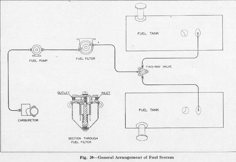
Above it has in MBC - 1 Below as in MBC-2
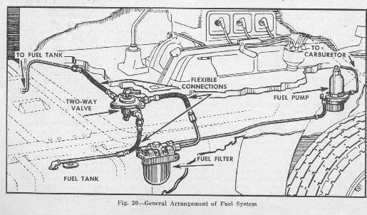
Link to MBC-1 and MBC-2 Fuel and Exhaust Manual Pages One of the first thing you'll notice is that the earlier manual has fifteen pages and the later manual has nineteen there also several changes that make the fuel and exhaust system pages more relevant to CMP's as compared with standard commercial trucks.
To the question of fuel line routing there are significant differences see the two photographs and at left it to say that they went from a generic to a specific vehicle layout.
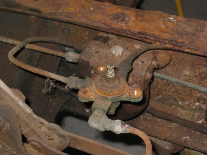
The same basic layout is used on both Pattern 11, 12 and 13 what I've found it be different on the twelve and thirteen from what is shown in the manual and the service bulletins is which have solid steel tubing and which have flexible lengths hose. Both of my trucks had solid steel tubing all the way from the tank to the two way valve the Pattern 13 had a flexible connection could have lost the n to the fuel filter while the Patter 12 had solid steel tubing connecting the selector valve to the fuel filter mounted under the driver .
The following photos with notes show the routing of the steel tubing from the fuel tanks two the selector valve.
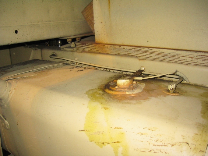
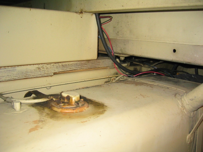
Note in the two pictures below picture below you'll note evidence of some leakage, the discoloration around the fuel level sender unit this is the result of the ethanol in today's gas dissolving the rubber in the cork composite gaskets I still have not found a reliable replacement.
This is the left and tank on the Pattern 13 with forward on the vehicle being to the left, steel tubing fuel line comes out of fitting on the tank goes directly over to the frame then parallel to the frame tour it's the from the truck to turn and pass through the hole in the frame. Note the rubber grommet to keep the fuel line from chafing on the frame.
This is the right tank or driver's side of the pattern thirteen with Ford on the vehicle being to the right in the picture again you can see the fuel line comes straight out of the tank with right angle to the frame and forward along the frame to the drama did hole the frame. On my pattern thirteen both of these fuel lines extended from the tank all the way to the fuel selector valve as a single piece of tubing. When I tried to reproduce the fuel line I discovered that it was not possible to feed the line through with the engine and transmission installed in the chassis and the cab in place I'm sure during normal construction the fuel lines were inserted on the production line when there were no obstructions.
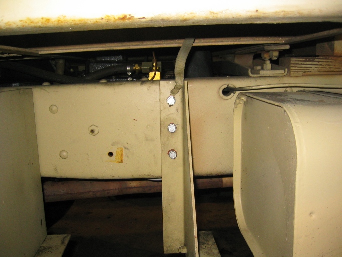
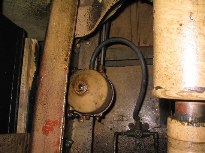
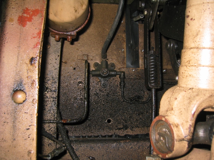
Again left ankle of a pattern thirteen fuel line goes through the hole in the frame and makes right angle turn to run across the floor of the cab. As there is a service bulletin concerning installing a flexible connection at this point I suspect that fatigue failures occurred at this location. In the picture below shows left side of frame front of truck to the bottom fuel line making its right angle bend up then to the rear. The rearward bend is to bring it in line with the fuel selector valve. [The white spin on oil filter is a remote will filter for the 261 cubic inch engine in the Pattern 13]
pattern thirteen driver's side
![]()
In this picture you can see the Pattern 13 1942 C60S at the beginning the restoration process with the cab having just been removed and you can see the layout of the fuel lines.
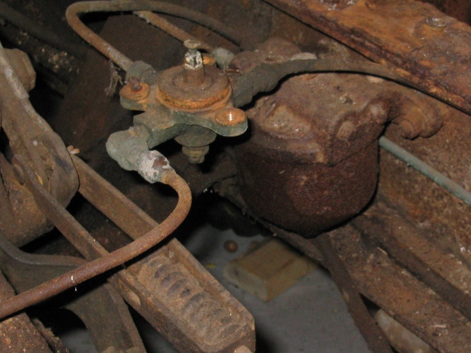
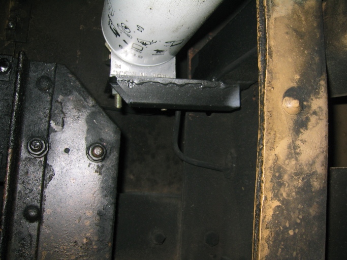
This picture is looking up at the valve seen in the picture at left.
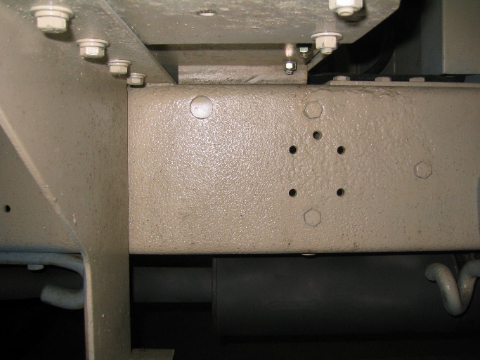
In the photo above you see the pattern twelve cab style on the left side just behind the running board bracket front of where the fuel tank support bracket would be located. In this case the 1 in. hole for the fuel line to pass through is yet to be cut [I had to replace the inner frame real with new material ]
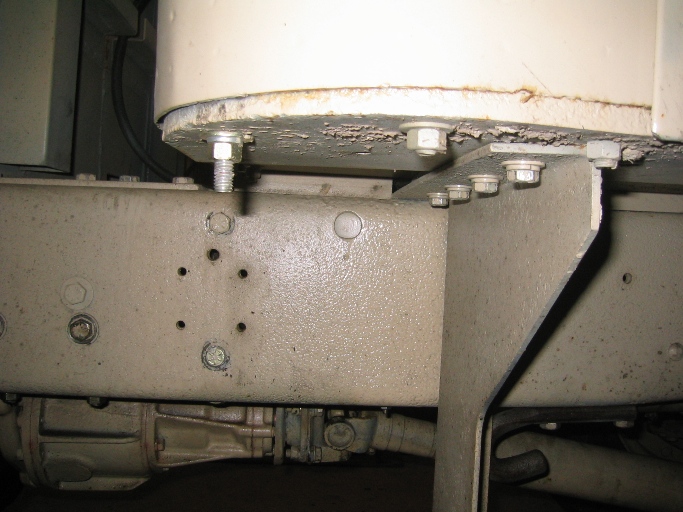
On the pattern twelve with the cab mounted almost directly to the frame the turn up in the fuel line once it passes through the frame real is much smaller than on the pattern thirteen. But again the fuel lines pass through the frame at the grommets holes and turn to run and lineup with the fuel valve.
In this photo is the driver's side of the pattern twelve same hole location