Engine Test Stand
May 17, 2012
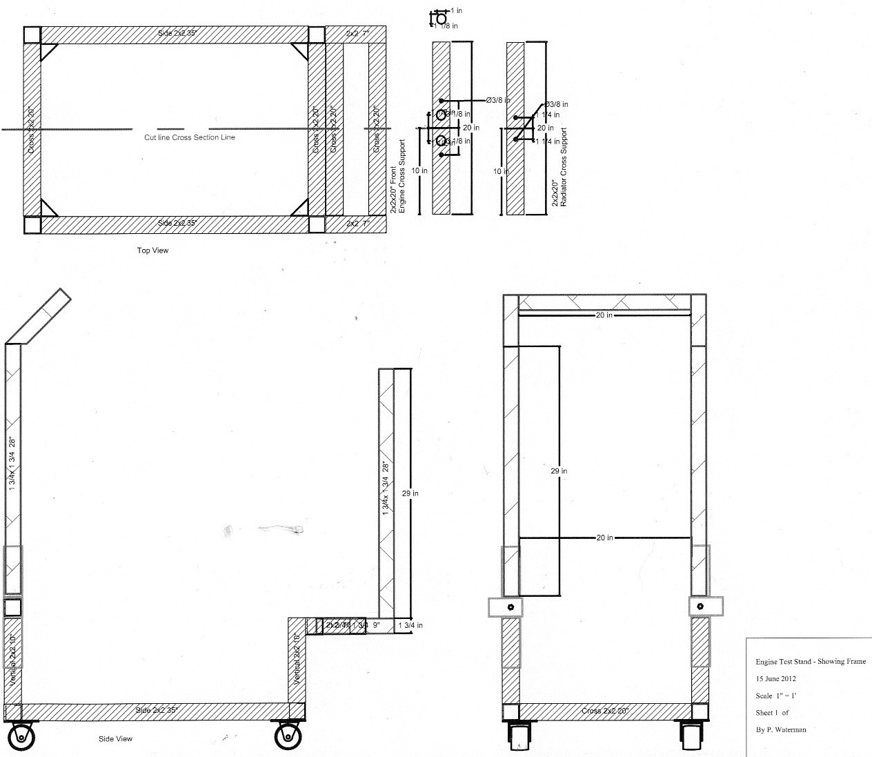
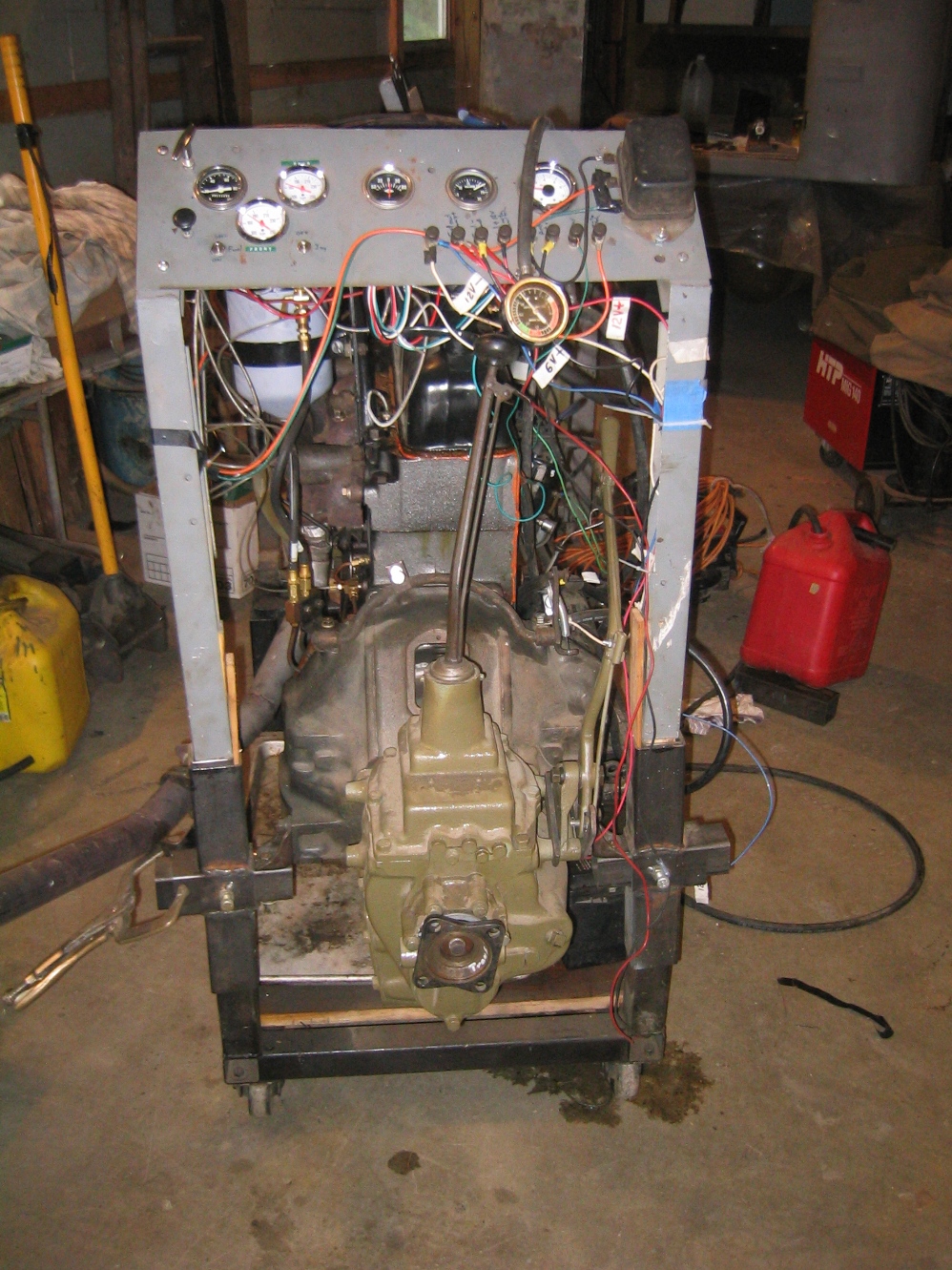
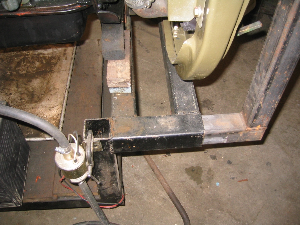
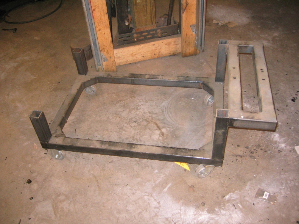
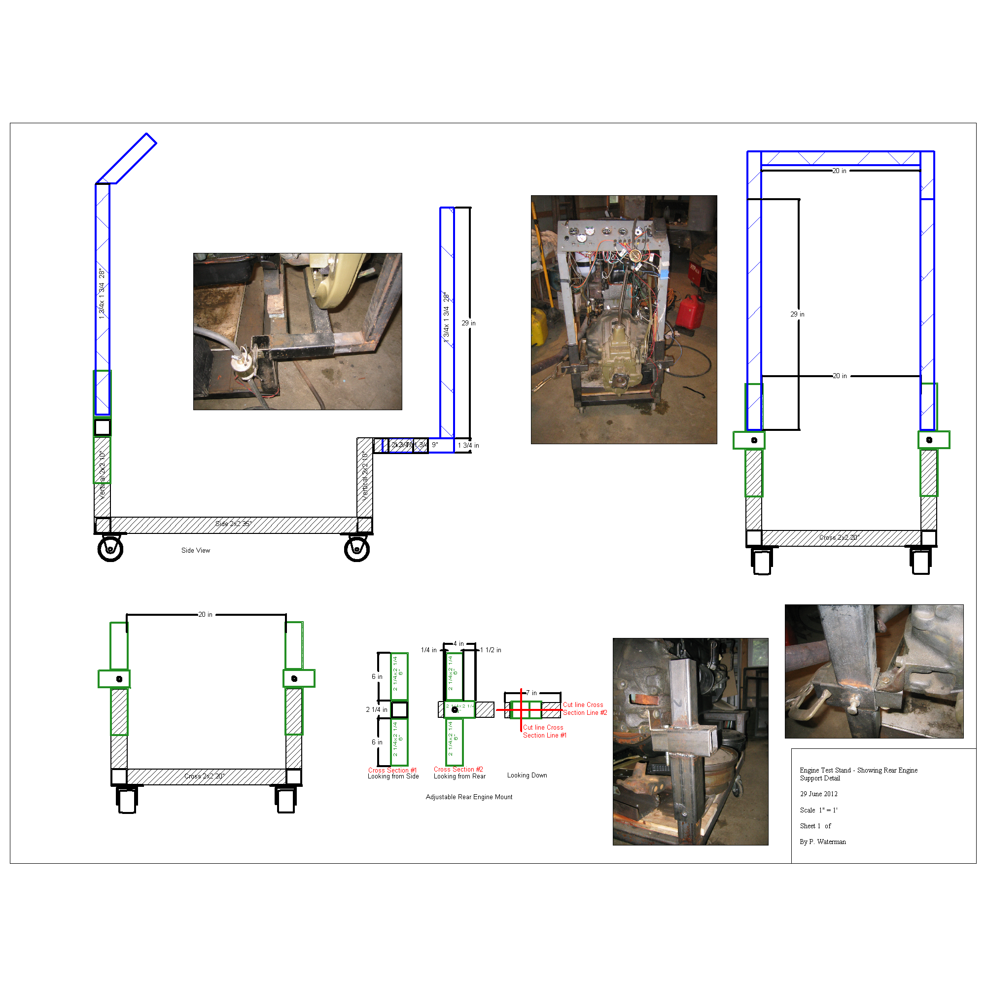
This engine test stand was originally developed to be used to test run stove bolt 6 Chevrolet engines, which are an inline 6 cylinder engine, though with some adaptation it will also take a V8 engine as well. One reason for the height and lay out is to allow the removal of the engine oil pan, or flywheel with the engine mounted on the stand. The length and width also had one other criteria was that the stand with engine would take up the minimum space.
Engine test stand is made from mild steel box tubing, primarily 2 x 2 x 1/8 inch with 1 ¾ x 1 ¾ x 1/8 and 2 ¼ x 2 ¼ x 1/8 th . The important thing is that the 1 ¾ x 1 ¾ x 1/8 slide inside the 2 x 2 x 1/8 and that the 2 x 2 x 1/8 slides inside the 2 ¼ x 2 ¼ x 1/8 th. Check with your steel supplier most wholesale suppliers will have samples. If necessary you can change to three sizes that will accomplish the same slip fit.
| Description of piece use |
Size
|
Length Inches
|
Quantity
|
|
Sub total
|
Feet
|
| Side rails |
2x2x1/8th
|
35
|
2
|
|
70
|
|
| Cross rails |
2x2x1/8th
|
20
|
4
|
|
80
|
|
| Verticals |
2x2x1/8th
|
10
|
4
|
|
40
|
|
| Front upper side rails |
2x2x1/8th
|
7
|
2
|
|
14
|
|
| Rear engine support slide adj |
2x2x1/8th
|
7
|
2
|
|
14
|
|
|
Total Length 2x2x1/8th inches
|
|
218
|
19
|
|||
|
|
||||||
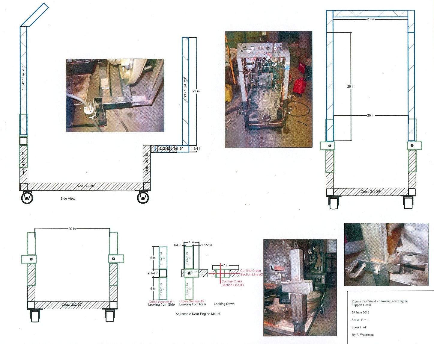
| Rear engine support verticals | 2 1/4 x 2 1/4 x 1/8 |
6
|
4
|
24
|
||
| Rear engine support horizontals | 2 1/4 x 2 1/4 x 1/8 |
4
|
2
|
8
|
||
|
Total Length 2 1/4 x 2 1/4 x 1/8th inches
|
32
|
3 | ||||
|
|
|
|
||||
| Radiator "L" supports verticals | 1 3/4 x 1 3/4 x 1/8 |
28
|
2
|
56
|
||
| Radiator "L" supports horizontals | 1 3/4 x 1 3/4 x 1/8 |
9
|
2
|
18
|
||
| Instrument Panel verticals | 1 3/4 x 1 3/4 x 1/8 |
28
|
2
|
56
|
||
| Instrument Panel cross | 1 3/4 x 1 3/4 x 1/8 |
20
|
1
|
20
|
||
Instrument Panel verticals |
1 3/4 x 1 3/4 x 1/8 |
9
|
2
|
18
|
||
|
Total Length 1 3/4 x 1 3/4 x 1/8th inches
|
168
|
14 | ||||
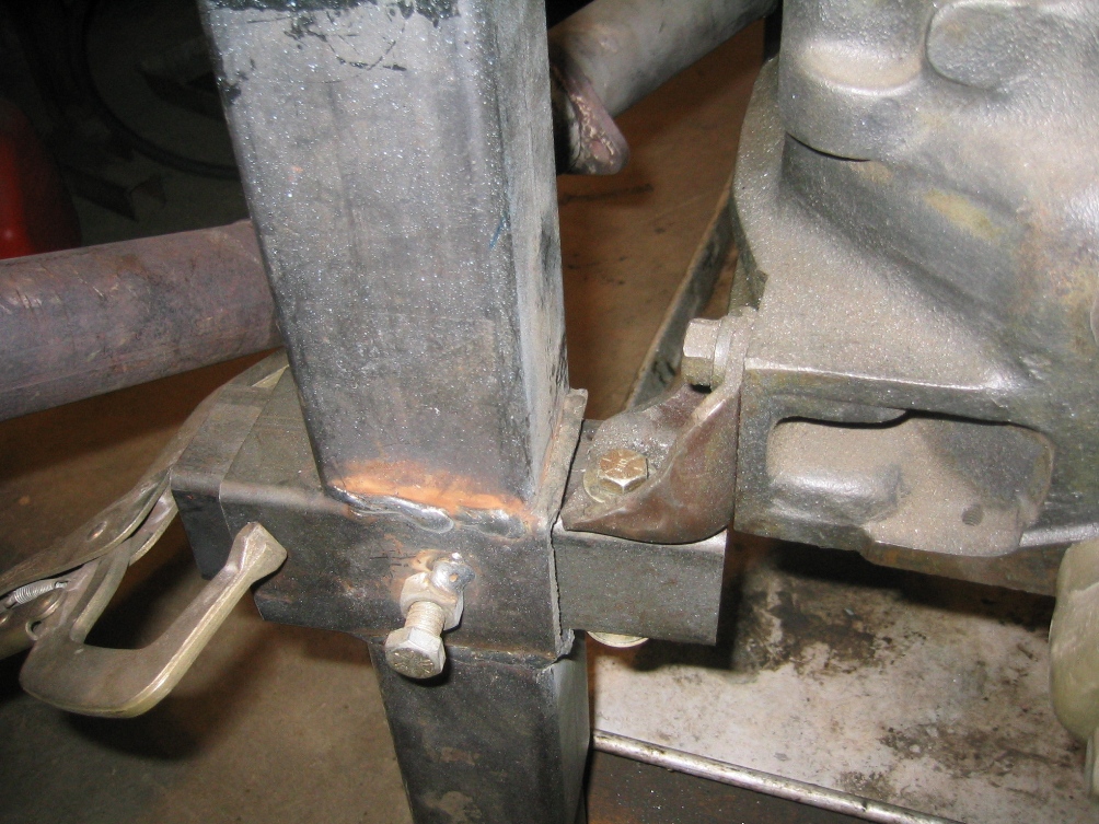
If you have a plasma cutter, power hack saw, or chop saw you probably
will want to buy the tubing in single lengths of tubing. But remember
that you are going to want to cut the ends square and accurately to have
a test stand that will sit square and that the slide fits will actually
work. Don't worry though if your lengths are +/- 1/8 just remember to
do your welding on a flat surface and use a good square to set all your
corners. Minor adjustments or unevenness of cuts can be correct in welding.
If you don't have a power method of cutting then, have all the lengths cut to lengths cut by supplier. Be sure to say you want them cut square (not torch cut).
Tip on welding, tack weld each joint then turn the part over and tack weld the other side. Then check that it is flat and square. Don't get carried away and run a nice two long weld on one joint before all the joints are tacked. A single long weld will warp. What seems to work best is to tack every thing then weld all the connections. This engine test stand was originally developed as welding project to teach welding. It is an excellent way to polish your welding skills if you have not done much welding.
General Notes:
1. I have now built 5 of these stands; the first one was so useful
and made it easy to move engines around shop that eventually I built 5
while teaching welding seminars.
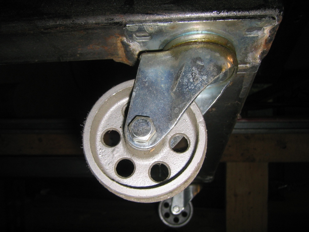
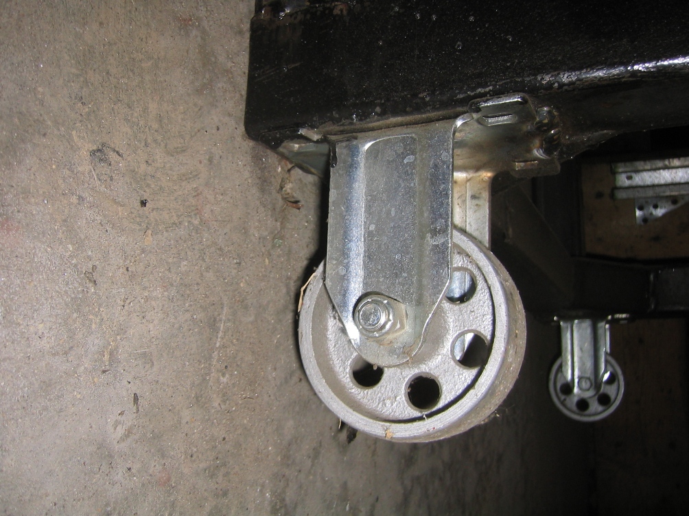
2. Caster selection I have tried a number of types of casters and for
my purposes a 3-4 metal caster has proven best for rolling on smooth concrete
and wood floors. If however your floor is not smooth or you need to be
able to roll the engine out side on rough surface dirt, or gravel you
probably will want to select a larger diameter and different design. Concerning
steering casters I have tried 2 non-steering paired with 2 steering as
well as 4 steering. The latter on anything but very smooth surfaces is
not as practical, and it also introduces more of tipping potential when
pushed sideways.
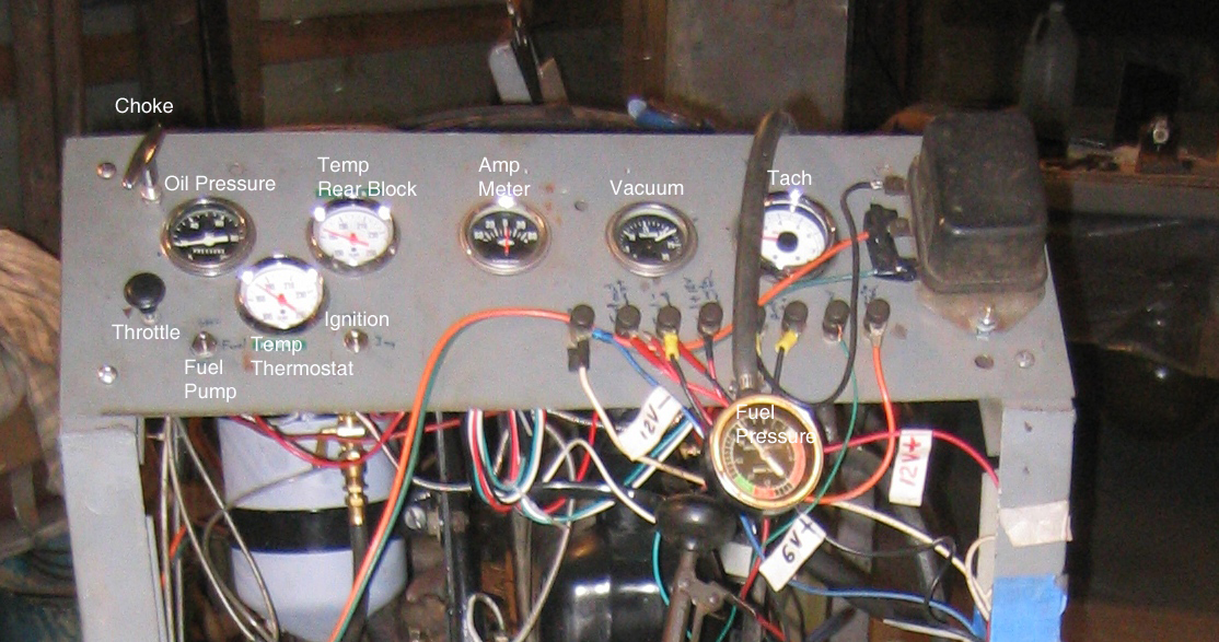
3. Instruments - the following are what I have found to be useful. of
these OIL PRESSURE and TEMPERTURE GUAGE are essential. The others can
be worked around if you have individual testing equipment that you can
clip on or connect. But if you are really going to run the engine in on
the test stand go ahead and buy the two inch gauges. In terms of lay out
of the instruments organize your panel so that all of gauges that have
electrical connections are at one end and all mechanical gauges are at
the other end. It is also important to remember to tape or protect all
connections so that they will not accidentally short out. Things like
mechanical temperature gauges with their long tubes going to the sensor
are quickly ruined when the metal tube shorts out on the terminals of
the amp meter.
a. Oil pressure; try to find gauges that will be at half scale at the operating pressure of the engine.
b. Temperature Gauges- either mechanical or electrical, suggest using which ever type the engine will have once mounted in the vehicle. I have added a 2nd gauge which allows checking at two points on the engine.
c. Amp Gauge- as one of the reasons for running an engine on the test stand in the first place is to also test adjust the generator and the voltage regulator both of these are included.
d. Volt Meter- though my test panel doesn't have one I think adding one might be useful, often have a multi meter reading the voltage as it is.
e. Vacuum Gauge - is extremely useful in testing an engine,
f. Tachometer- very useful in testing and also making sure you don't over speed the engine during breaking in.
g. Fuel pressure Gauge- amazing how many simple problems this help you spot that other wise would drive you crazy.
4. Other Controls and Taps on the panel
a. Hand or Manual Choke
b. Hand throttle
c. Ignition switch
d. Electric fuel pump switch
e. Wiring connection terminals - these bring the electrical connections from gauges and switches to the front of the panel where it is easier to make connections. These are the connections on my panel;
i. Battery (s) ground connection
ii. Fuel pump power + out to pump (connected to switch behind panel)
iii. Fuel pump ground
iv. Power to fuel pump switch (connected to switch behind panel)
v. Amp Meter + connection (connected to meter behind panel)
vi. Amp Meter - Connection (connected to meter behind panel)
vii. Power into ignition switch (connected to meter behind panel)
viii. Power out to coil (connected to ignition switch behind panel)