Engine Test Stand
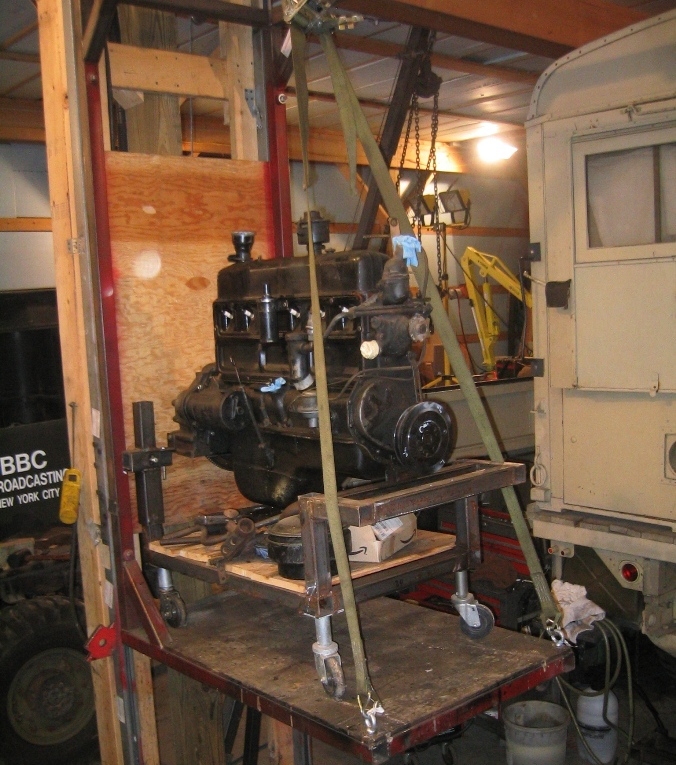
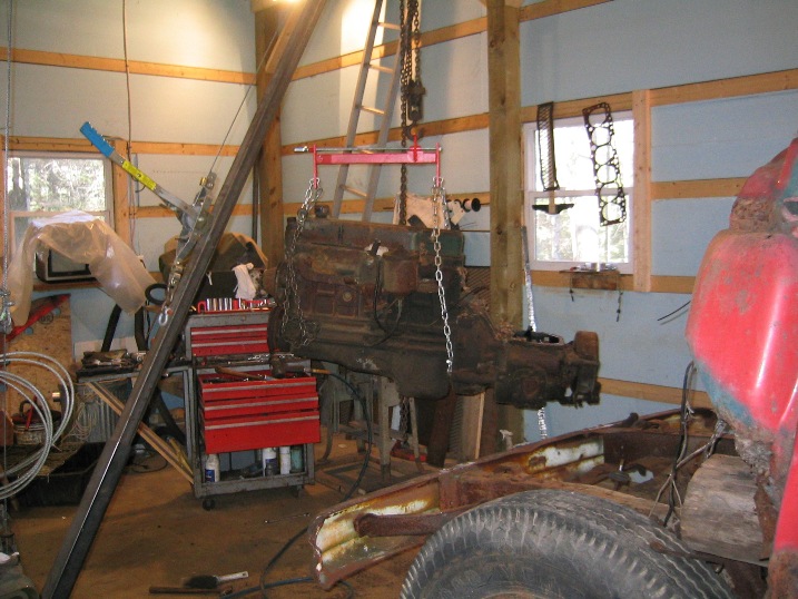
Working on the engine, when installed in the CMP, is so constricted by the semi cab over design, that a test stand to setup and run the engine prior to putting it into the truck seemed like the solution. The test stand is fabricated out of 2x2 box tubing and is on heavy duty casters.
The positioning of the mounts and bolts is the same as in the truck which also helps in setting up engines that did not originally come from a CMP as in case the engine is 1952 216 engine which has slight variation in the water pump.
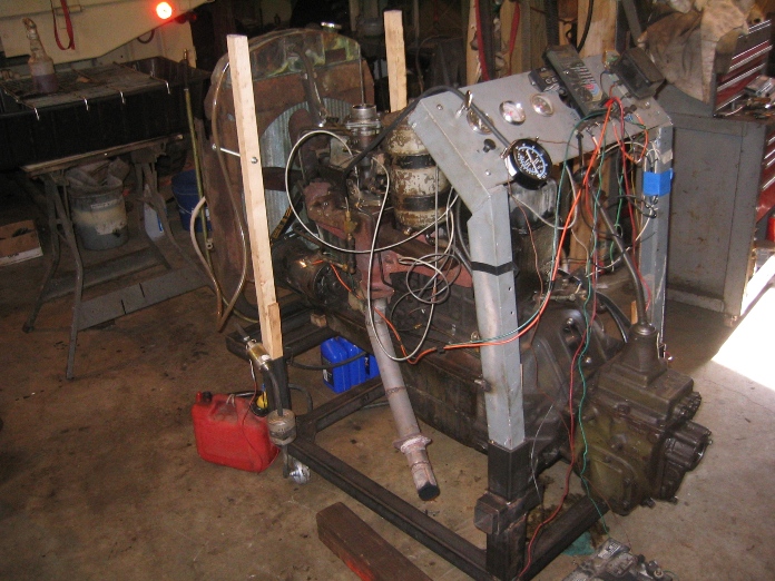
Instrumentation on the stand includes oil pressure, temperature, amp meter, and vacuum gage on the instrument panel loose mounted instrumentation includes a fuel pressure gage in the fuel supply line, and tachometer.
The stand also has a water jacket heater which brings the engine up to 150 making starting easier. Also an electric fuel pump is used to insure that the carburetor is primed prior to hitting the starter.
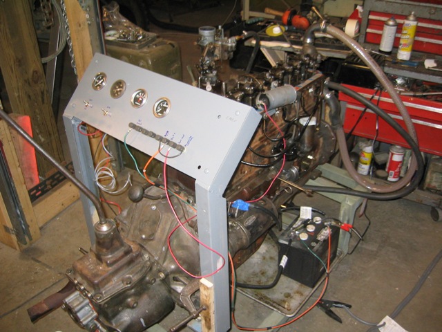
The instrument panel also has provision for mounting the voltage regulator which allows full testing of the generator and charging circuit.
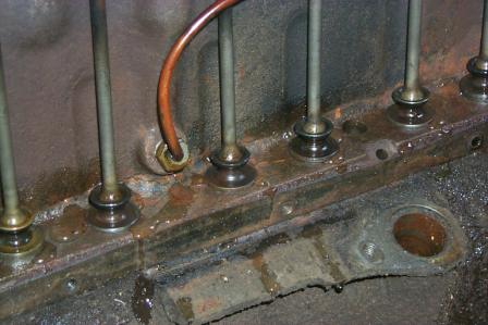
The testing on the engine in this case has identified the following problems:
- Minor leak in the seam of the lower radiator outlet
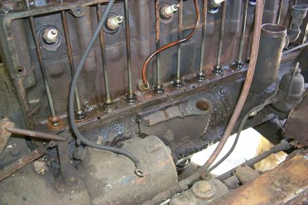
- Side panel oil leak, which will require removing the side panel and removing the warping caused by years of over tightening the pan bolts to try stop oil leaks. The side cover is one of the weak points of the 216 design after 50 years they leak oil
- Generator bracket that is out of line, early generator on later engine.
- One noise coming for the engine that doesn't seem quite normal. A hollow clank coming from the rear of the engine.
- Oil leak in the transmission case bolts that need to have the threads sealed
- An overly rich running carburetor that would not ideal down. Temporary fix for this was borrowing a known good carburetor from one of my other trucks.
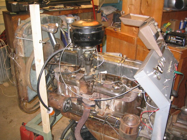
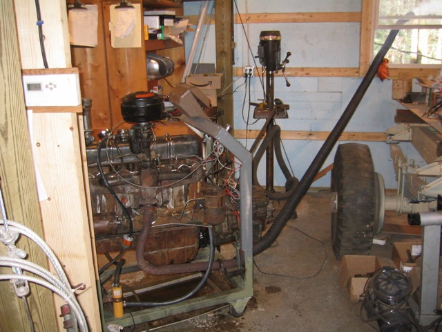
The exhaust system for the test stand is still under development. I have a fume extraction system that I use when welding or cutting in the shop. This is also, what I use when running any vehicle in the shop it sucks more fumes than engines put out, which pumps the carbon monoxide and fumes out of the shop. However, the overly rich engine plugged the filter on the fume extractor so what is picture at right is the old-fashioned pipe out the window.
Video of 216 cu.in.Engine first running For DSL or highspeed connection
Moved to YouTube 5 Feb 15
There was a noise that I could hear very faintly, but with the human ear unaided it is hard to localize the source.
The diagnostic trick once the sound was localized was to short out the individual spark leads to listen for change. What you hear as a result sounds for all the world like you are hitting the engine with a hammer.
Well I've got another engine up on the test stand now a 235 cu. in.
New Video of 235 running March 18, 2011 These are High Resolution large files down load if you have a high speed connection.
3-18-11 235 running 001
3-18-11 235 running 002
While a restoration purest at heart I'd rather keep the original 216 cu.in. Chevy Six in all my CMPs the reality of today's road conditions of higher speed less patients drivers made up engining a nearly 10,000 lb truck became a necessity.
The Pattern 13 BEAUTY got a 261 cu.in. while the Pattern 12 3 Ton, will get the 235 cu. in. still have some work to do before it is ready to mount in the truck. Because it is so difficult to work on the engine of a CMP ones it is installed in the truck I try to do all my engine testing and set up on the test stand.

While the 235 is running in I've been working on the 261 engine which has the large full flow oil filter, while the In the picture below you can see the original full flow oil filter unit as used on the later 261 chevy truck engine. As I'm preparing the engine to start running it in I was working on the oil filter unit, comparing the original with the replacement spin-on type filter unit I plan to use. Couple of things I noticed one the original has a bypass valve if the the filter becomes plugged. It would seem a good idea as the new spin-on filter unit doesn't have this feature. So figured I'd find out at what point does the bypass open and discovered that basically always flowing oil and never really closing completely. With this in mind I guess the spin-on with no bypass is a more positive way of filtering the oil. It also means that if any of you are going to reused the original 261 filter units be sure to clean and check the filter bypass.
Additional Information 2011, I now have four of these test stand as it makes it so much easier to store and work on engines. I have used wooden cradles but have found that these are vastly superior One important thing I have learned is DO NOT USE rubber or composite wheels no mater what they say they take a set and end up flat spotting which makes it hard to get a stand has been sitting for any length of time are. Metal wheels work much better Particularly on smooth floors.
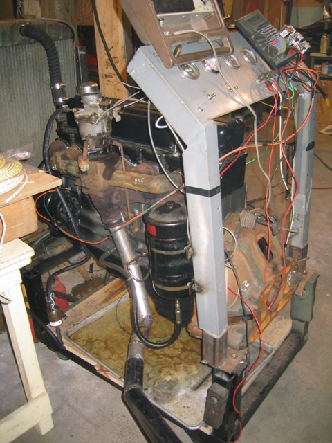
Picture below left is the 1st generation rubber wheels and awkward mounting for the instrument panel
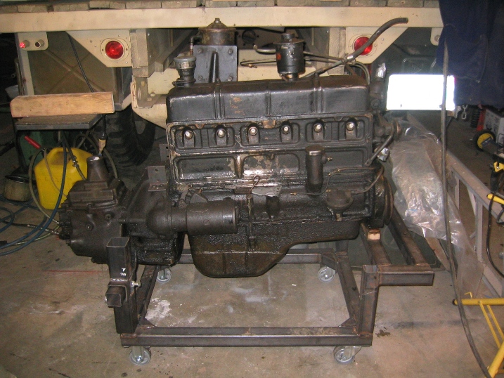
Right 2nd generation redesigned rear mounting much more adjustable with better instrument panel mount
Above & Below 3rd generation steel wheels
Link to Test Stand Design Page Drawing and Detail Photos
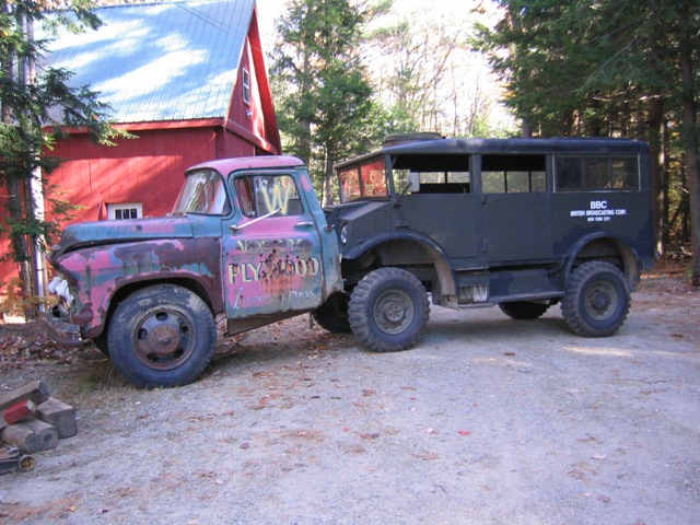
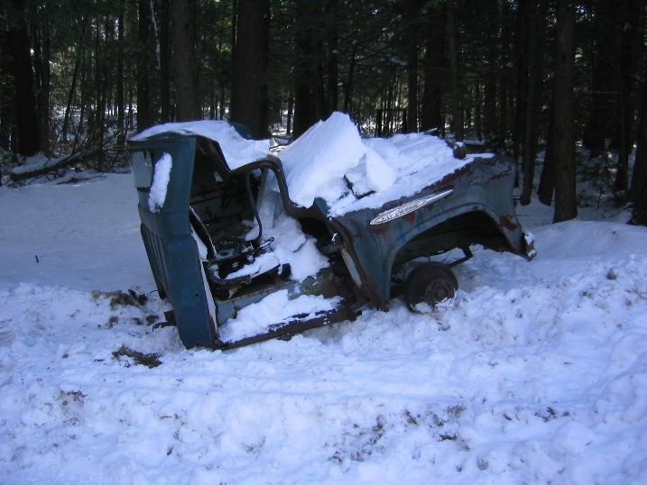
The picture below is the engine as I was removing it from the donor truck. The picture below right is the 235 donor truck being moved into the shop. While the 261 donor truck was in a little rougher condition see picture below. I had been trying to get both of these trucks out of an old junk yard for 5-7 years they were both way in the back and it wasn't until the junk yard was being cleaned out everything went for scrap that I was able to have the two trucks dragged out.
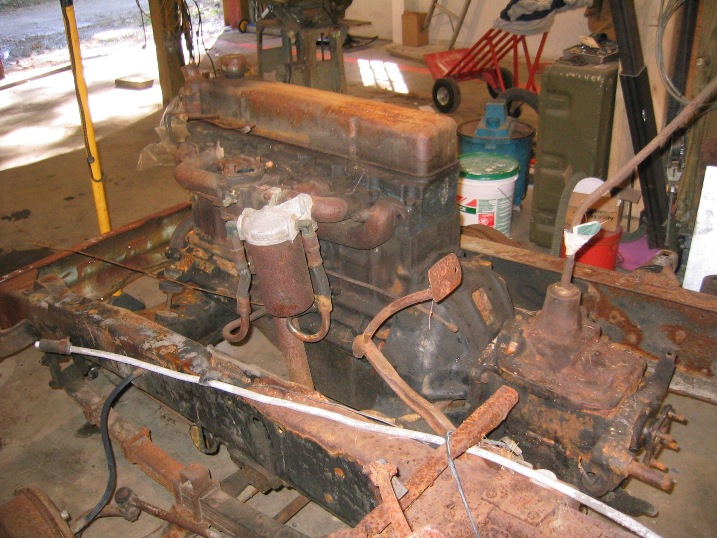
Below is the 235 as it came out of the donor truck
What's rebuildable?
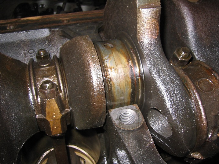
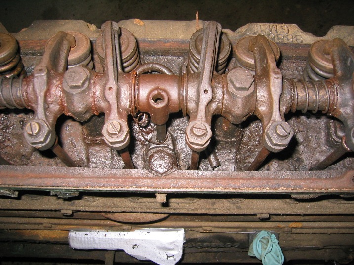
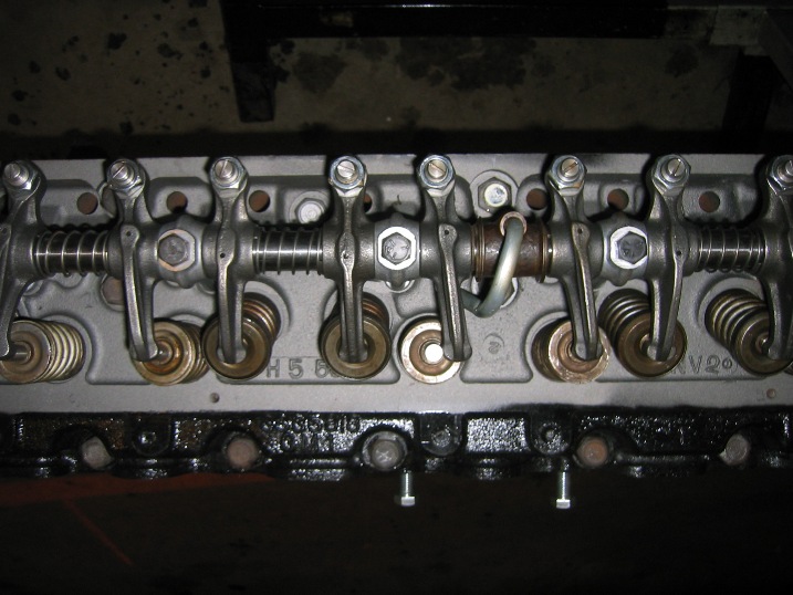
But back to rebuilding the 235 and the 261 that I'm currently getting ready are prime examples of what is practical to rebuild. The pictures below 261 on the left and 235 on the right give and idea of some of the issues. The 235 was found to need a complete rebuild and basically the entire valve train including new cam, cam and crank gears, lifters, push rods rocker arm assembly and valves. Why? look at the picture of the center section of the rocker arm unit. This nasty condition was caused by failure of the oil tube and extreme sludge build up someone even had tried to wire the tube back in to place, the rocker arms had obviously run dry for a long time with signs of having even seized. The next 235 picture shows the same head after cleaning cutting in new valve seats and complete new valve train. You might notice that #3 intake valve rocker arm doesn't lineup, even new parts sometimes are wrong the new rocker arm assembly had one wrong rocker arm. This was not so quickly corrected as while ordering an entire rocker assembly had easy, getting them to realize that one arm was wrong took 2 weeks and 3 photos. In the end it would have been easier to send the entire assembly back instead of getting them to send just one part.
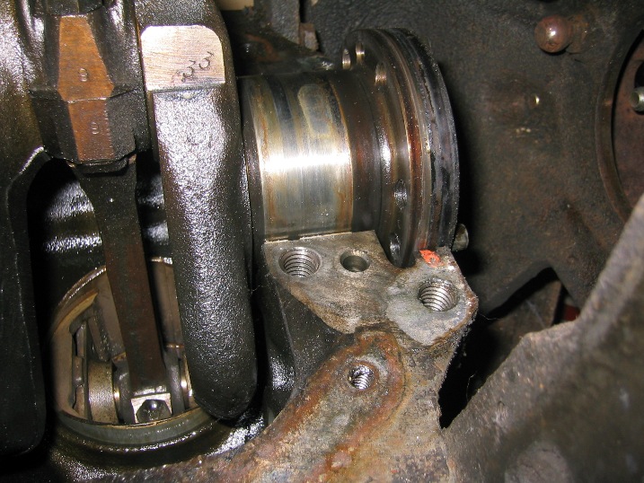
The biggest issue on the 261 was the condition of the crank which was poor just from many, many years of sitting in the junk yard. But in the end this turned out to be just an issue of regrinding and inserting new bearings.
`58-62 -- 261 cubic inch
`49-58 -- 235 cubic inch